Learn more about static oring groove design for rod, cylinder, and piston orings from Marco Rubber, the industry leader in standard and custom orings Welcome to the world's largest database of specialty and standard sealing productsORing Design Guide Machining Specifications ID Stretch/OD Interference ID OD C/S ORing Rod Gland Ø Gland Ø Piston For hydraulic and pneumatic piston sealing applications The Oring ID should be stretched between 2% and 5% for dynamic applications and 2% and 8% for static applications For OringsHighPressure BiDirectional Hydraulic Piston Seal Oringenergized cap seal design The specially designed hard wearing, 60 shore D, selflubricated polyurethane cap is much easier to install than PTFE cap seals and provides high extrusion resistance Further, the design provides a fluid reservoir between the two beveled sealing lips which
1
O-ring piston seal design
O-ring piston seal design-Piston TSeals Designed to fit imperial o'ring housings in accordance to ISO3601 (BS1806/AS568A o'ring sizing), Tseals are an ideal replacement for o'rings The Tshaped sealing element serves as a slide ring that's highly resistant twisting and spiral failureDepending on your application you can have the groove be cut in
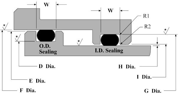


Dynamic O Ring Design Chart Marco Rubber Plastics Custom O Rings Supplier
Design Chart 53 provides the basis for calculating gland dimensions for a floating pneumatic Oring design Standard Oring sizes have the dimensions calculated and are listed in table 53 To use the table, start with the diameter of either the bore/cylinder or the pistonA perfectly designed Oring seal is of little use if the Oring is damaged during installation To prevent installation damage for pistontype and rodtype seals, we recommend a 15° chamfer on the bore or rod The Radius Containing Surface Break Edge Sealing Surface Wall Angle Sealing Surface AS568 ORing CS Chamfer Length Series Inches mmOring groove design is a key consideration in the oring selection process Browse design considerations and recommendations for static face seals, metric orings, static dovetail orings, static rodpiston orings and dynamic rodpiston orings Once you find the right oring groove design you can easily order online from the world's largest
An Oring seal is used to prevent the loss of a fl uid or gas The seal assembly consists of an elastomer OIf you are designing a face seal, select the ORing with an inside diameter which will position the ORing on the side of the groove opposite the pressure Click here for more information on face seal groove design Note the ORing inside diameter for the next step Calculate the Seal Stretch Using Equation 1, calculate the installed seal stretchThe grooves ensure good lubrication and reduce friction The rear face of the Kefloy® ring has a concave shape This ensures a good contact to the ORing and prevents the seal from turning with the piston The seal design ensures an efficient leakage control over the entire pressure range from 0 to 30 MPa
Seal & Design Established in 19 by Dean T Penman, Seal & Design Inc has established itself as an industry leader in the sealing and gasketing industry Seal & Design is a leading manufacturer and distributor of die cut gaskets, seals, orings, and molded rubber products Dean's original philosophy included exceeding customer expectations An Oring, also known as a packing or a toric joint, is a mechanical gasket in the shape of a torus;This dynamic oring groove design guide for rod and piston glands will help you find the dynamic oring that’s right for your application Once you know the exact oring you need, you can quickly and easily order online from the world's largest inventory network ORing Size Charts Oring, xring and square ring size charts
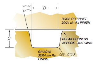


Groove Design O Ring Seals Minnesota Rubber Plastics


Aircraft Hydraulic System Seals Types And Installation Aircraft Systems
Hydraulic Piston Seals › Piston Seals or Piston Rings are used in hydraulic cylinders for fluid sealing They are internal to the cylinder head and seal against the cylinder bore, preventing fluid from flowing across the cylinder head This allows pressure build up on one side of the piston, making the cylinder extend or retractERIKS standard ORings and load them also into your created design info chemical volume swell (%) cross section diameter (mm) ISO 3601 free Calculate Results Reset calculatorIt is a loop of elastomer with a round crosssection, designed to be seated in a groove and compressed during assembly between two or more parts, creating a seal at the interface The Oring may be used in static applications or in dynamic applications where there is relative
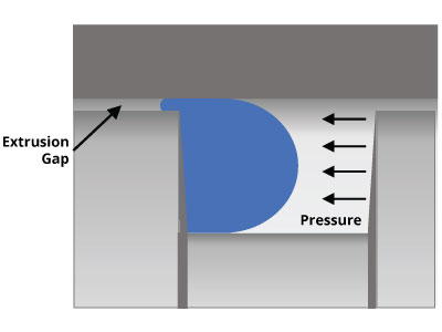


O Ring Groove Design Global O Ring And Seal


Sealink Sealing Mechanism Lubricant Free Mechanical Seal Design Sealink
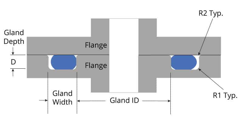
A piston design where two singleacting seals on the piston for a doubleacting cylinder are used can easily give rise to a breakdown The reason is that a very high pressure can be trapped between the seals Piston seals, both single and doubleacting, can be designed for and used with integrated or separate backup rings and guide rings The profile of the T621 rod seal's NBR energizer ensures that the primary sealing lips maintain contact under low or nopressure conditions while ensuring proper sealing at higher pressures Challenges for Rod Seals Pistonrod seals require a different design because one side seals against the ambient environmentO'ring Groove Design As important as the o'ring seal itself is the groove that the o'ring seats into The groove must be designed to accommodate not just the o'ring size, but also its intended usage;


Http Practicalmaintenance Net Wp Content Uploads Working Design Considerations And Maintenance Of O Rings Pdf


Mpsq Piston Seal Assemblies Hercules For O Rings Hydraulic Seals Cylinders
Cating ORing Seals 5312 ORing Glands for Industrial Reciprocating Seals Design Chart 52 provides a reasonable basis for calculating reciprocating Oring seal glands Design Table 52, which follows it, contains recommended gland dimensions for the standard AS568A Oring sizes The major difference from the military gland dimensions (DesignCalculate minimum squeeze needed on ORing Use total value from step 1 multiplied by a safety (0055" x 4) factor of 4 Calculate cross section for ORing to provide a Squeeze of 15%, typical for a piston seal Select closest standard cross section for ORingTwo NBR "O" ring NBR backup ring sets (A) (photo below left);
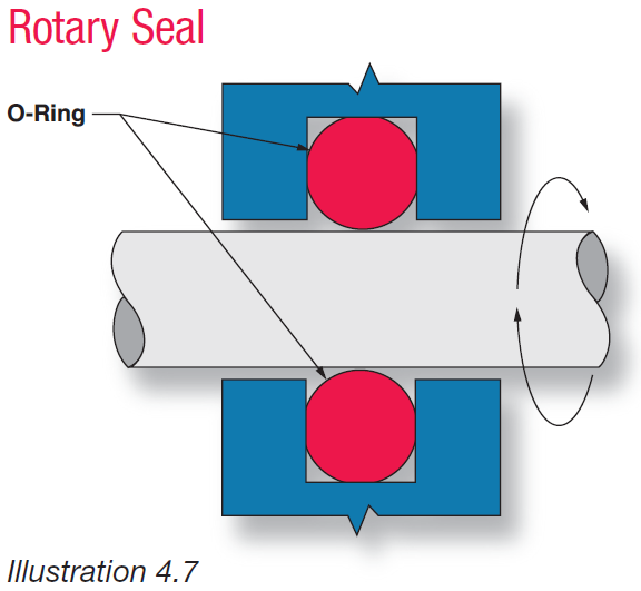


Fundamental Of O Ring


Seal Solutions Guide
A perfectly designed Oring seal is of little use if the Oring is damaged during installation To prevent installation damage for pistontype and rodtype seals, we recommend a 15° chamfer on the bore or rod The chamfer must be long enough to ensure that the Oring sees only the chamfer when it is installed Facetype seals do not require designThe KB21 profile is a symmetrical sharplipped ORing energised UCup seal and is commonly used in the hydraulic repair market as it can function in both rod and piston applications The ORing energiser in this seal provides further sealing force across the sealing lips to ensure leak free performance even Read MoreSince in this application the sealing is occurring on the bore, use the Bore column to look up the seal size for a 3000″ bore The correct seal is a number 4 149 (with the 4 prefix signifying a QuadRing® Brand seal) Note the seal inside diameter, which is 2800 ±0022 This will be used below 9 Calculate the Installed Seal Stretch
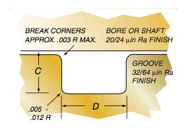


Groove Design Quad Ring Seals Minnesota Rubber Plastics


The Function Of Hydraulic Cylinder Seals Custom Hydraulics Design
Cal drive belts More information, including design criteria on Oring drive belts and their application will be found in ORing Applications, Section III 12 What is an ORing Seal?The oring gland design is more complex for radial seals and requires both the piston and the bore to have precise geometry The bore and the piston have to be concentric to one another One of the faces will be completely smooth and one will have an oring groove cut into it;Rubber Seals, Sealing Devices & ORing Seal Design Apple
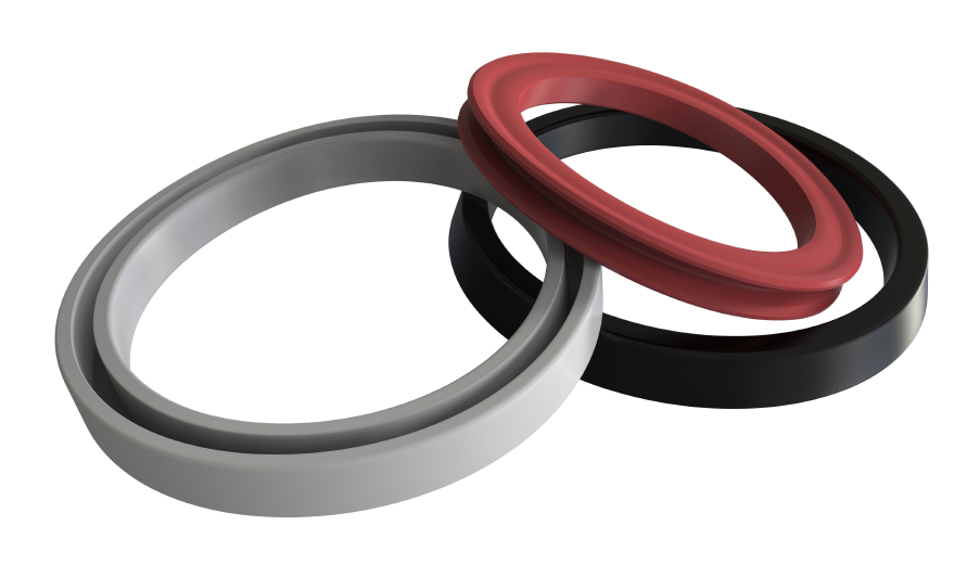


Types Of O Ring Applications
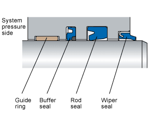


Wiper Seals Skf Skf
Parker´s ORing Selector is an engineering tool which offers Oring material and size selection combined in one tool Both are interlinked, thus ensuring the best possible combination of the calculated Oring size and material choice The ORing Selector covers both imperial and metric standards Service Conditions & Material SelectorBe it dynamic or static operation, radial or axial loading, vacuum or high pressureORing Groove Design 1 The following sizes are not normally recommended for dynamic service, although special applications may permit their use 2 Clearances shown are based on 70 durometer materials The clearances must be held to an absolute minimum consistent with design requirements for temperature variations and should not exceed the


Hydraulic Compact Piston Seal Tpm
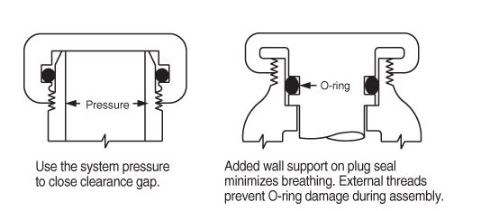


What Are Static Seals Hot Topics
Now, follow the steps below to design your own oring seal and oring groove Step 1 Choose your rubber properties by going to our Oring Material Guide section Step 2 Make sure that the material you choose will withstand the temperature of your system by going to this rubber temperature range chart Step 3 If you have a choice between a rod and piston seal, it's better to go with a piston seal, because the grooves are much easier to machine and inspect The biggest weakness of radial Oring seals is that the clearance between components creates a path for the Oring to extrude due to the pressure acting on itFastDashTM Oring Piston Seal Design Guide Enter the "A" diameter (ie bore diameter), Press the "Submit" button, The appropriate dash no orings will be


Fep O Rings Trelleborg Sealing Solutions
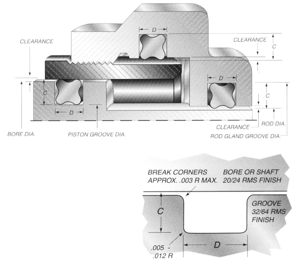


Quad Ring Groove Design Daemar Inc
Reciprocating seals are a dynamic version of either a male radial or female radial Oring design In a reciprocating seal, there is relative reciprocating motion (along the shaft axis) between the inner and outer elements This motion tends to slide or roll the Oring, or sealing surface of the Oring, back and forth with the reciprocal motionIn both the standard piston accumulator and the piston accumulator with indicator rod seals kits, for the current designs (in the sealsThere are two types of radial designs 1 Male or Plug the Oring groove is located on a plug which is inserted into the housing or cylinder (fig 123) 2 Female or Tube the Oring groove is located in the housing or cylinder and a tube is installed through the Oring lD (fig 124) Male or Plug Seal design is based on
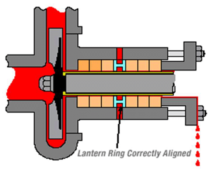


Shaft Seals For Rotating Shafts


O Rings O Yeah How To Select Design And Install O Ring Seals Tarkka
The Groove Width GW should therefore be about 15 times the ORing crosssection diameter to accomodate this axial expansion, Design Guidelines for Axial Seals ORing design for axial seals is similar to that for radial seals, with the important points summarized below The ORing must be compressed by a predetermined amount, and thisIn both the standard piston accumulator and the piston accumulator with indicator rod seals kits, for both the current and the old designsTwo PTFE guide rings (B) (photo below right);Learn about dynamic oring design for applications involving pistons, rods, and more View oring options from Marco Rubber and order dynamic orings online Welcome to the world's largest database of specialty and standard sealing products


A Simple Guide To Radial Seals Sealing Fundamentals Parker Hannifin


Design Of Oring Seals Design Of Oring Seals
2 Piston rod seal The piston rod seal , also called Ucup, is the main piston rod seal and is installed inside the end cover of the hydraulic cylinder to prevent leakage of hydraulic oil The piston rod sealing ring is made of polyurethane or nitrile rubber In some cases, it needs to be used with a supporting ring (also called a retaining ring)O ring piston seal design, Wholesale Various High Quality o ring piston seal design Products from Global Sodium Tripolyphosphate Suppliers and o ring piston seal designMETRIC ORING GROOVE DESIGN Contact Us For Assistance Or Samples Click Here and contact us today to receive a free quote or if you have any questions regarding sizing × Dismiss alert Metric oring groove dimensions are listed for the most common metric cross sections with and without backup rings We have included Static, dynamic,
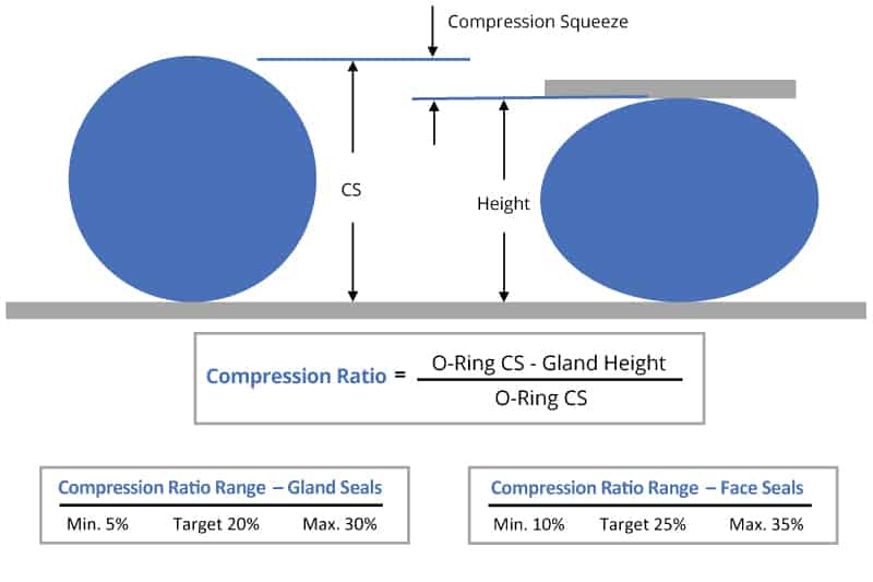


O Ring Groove Design Global O Ring And Seal


O Rings O Yeah How To Select Design And Install O Ring Seals Tarkka
The ERIKS Oring design calculator features the calculation of • oring dimensions for the use in a specific groove • groove dimensions for the use of a specific oring • evaluation of both, any combination of oring and groove for axial seals with inner or outer pressure, piston seals and rod sealsORing Installation Design and Specification For Dynamic / Reciprocating Applications Piston / Rod ORing Gland / Groove Installation For male / piston application Typical Reciprocating / Dynamic ORing Static Seal Glands / Grooves See "Gland / Groove Detail" above OThe Oring calculator tool is intended to form the basis of an oring installation, and assist with selection of oring and hardware dimensions Recommendations are based on available technical information, and are offered as suggestions only, any reliance placed on such information by the user is strictly at the user's risk
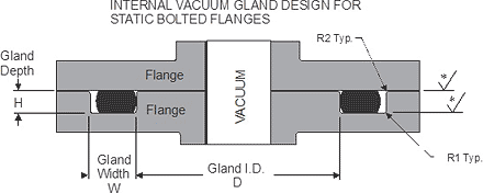


Static O Ring Face Seal Groove Design Guide


Enhancement Of Seal Life Through Carbon Composite Back Up Rings Under Shock Loading Conditions In Defence Applications Sciencedirect
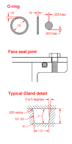
Oring seal The tables at the right and the diagram below provide the recommended gland design parameters In addition, the gland surfaces must be free from all machining irregularities, and the gland edges should be smooth and true and free of nicks, scratches, and burrs A perfectly designed Oring seal is of little use if the OringOrings are the epitome of elegant engineering The ring itself costs only a few cents, and the groove it goes in is simple and easy to manufacture But despOne general guideline for good Oring application and design is to maintain a range of % sqeeze on the Oring (~1040% for static and no more than 30% for dynamic) No less than 75% of the seal crosssection should be contained within the groove to ensure the seal does not "roll" or extrude out of the groove


Quad Ring Seals X Ring Static Seals Trelleborg
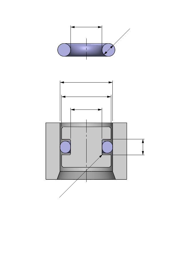


O Ring Calculator Ceetak Sealing Solutions
Preliminary Oring Design Considerations An oring is a simple and versatile ring shaped packing or sealing device Having a circular cross section that functions as a seal, in both static and dynamic applications, by being compressed between the mating surfaces comprising the walls of the gland, in which it is installedPiston Seals The main function of a piston seal is to provide enough resistance in order to maintain the hydraulic pressure necessary to make the piston move They are internal to the cylinder head and seal against the cylinder bore, preventing fluid from flowing across the piston Piston seals for hydraulic cylinders separate the two pressureA static Oring is any oring designed to contact with two or more surfaces that do not move relative to one another, whereas a dynamic Oring is one that helps form a seal between moving parts On the whole, static orings are created from less robust and hardwearing materials than their dynamic equivalents


A Simple Guide To Radial Seals Sealing Fundamentals Parker Hannifin
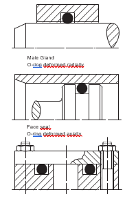


2 Design And Detail Information O Rings Stock O Ring Webshop
Of the Oring between the piston and cylinder or shaft and groove, up to 5,000 psi using 90 durometer compound ROTATING SEALS (Design Chart 5) Rotating seals should be limited to shafts having the following maximum rotational speed Shaft Diameter 125 280 – 350 ft/min Shaft Diameter 281 625 – 400 ft/min


Back Up Rings O Rings Performance Sealing Inc


Oring Ehandbook


Oring Ehandbook


Seal Design O Ring Design O Ring Design Guide
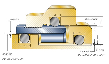


Groove Design O Ring Seals Minnesota Rubber Plastics
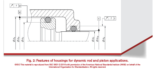


History Of The Iso 3601 Series Of Standards For O Rings Fluid Power Journal


Dynamic Reciprocating Gland Design Dynamic O Ring Gland


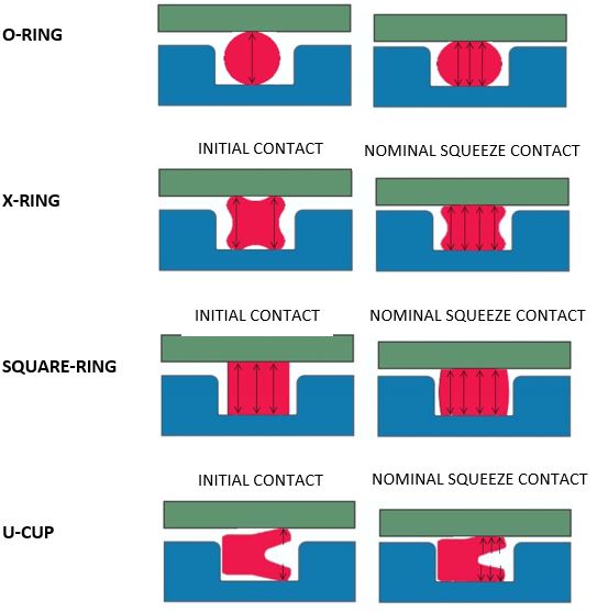
What You Need To Know About Dynamic Seal Applications Hot Topics


Sealcalc
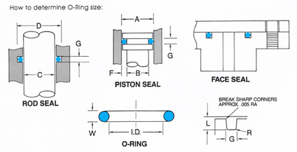


O Ring Groove Design
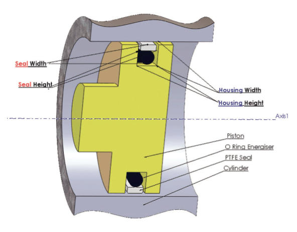


When It Comes To Seals And O Rings Martin S Rubber Are Flexible Process Industry Forum
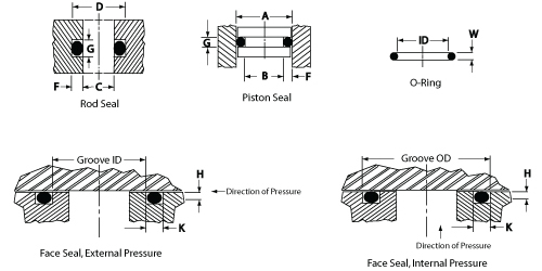


O Ring Groove Design Daemar Inc


Untitled Document


Buna O Ring O Ring In Houston And Minneapolis Dichtomatik


Mapa 22x30x3 Hercules For O Rings Hydraulic Seals Cylinders


Hercules For O Rings Hydraulic Seals Cylinders


1
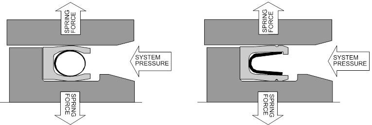


Spring Energized Seals Teflon Ptfe Seal Groove Design Guide


Hydraulic Piston Seals Piston Seals American High Performance Seals
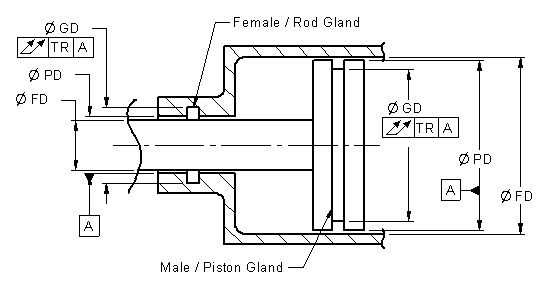


O Ring Installation Design And Specification For Dynamic Applications Engineers Edge
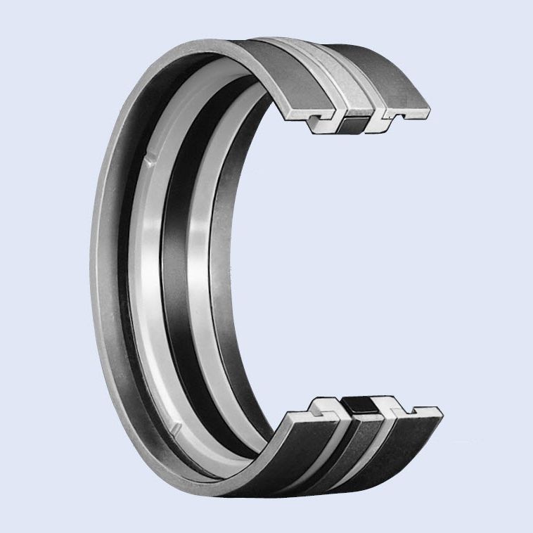


O Ring Seal Gd1000k Series Hunger Profiled Nbr Ptfe
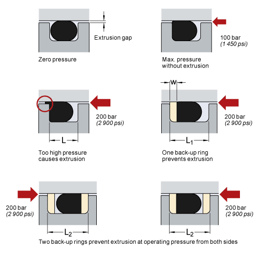


O Rings And Back Up Rings Skf Skf
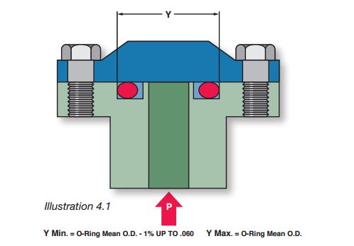


What Are Static Seals Hot Topics
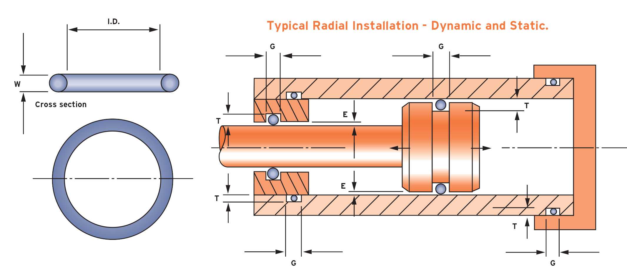


What Is An O Ring Selection Material And Storage Barnwell


Purpose Of The Piston Seal Youtube


Seals Eastern O Ring Piston Seal Design Guideline


What You Need To Know About Dynamic Seal Applications Hot Topics


1


1


Applications Technology Sealing Elastomers In The Semiconductor Industry Are Used In Hundreds Of Applications Unique Environments Such As Vacuum And Plasma And Demanding Requirements For Contamination Place Great Importance On The


1


Mating Ring An Overview Sciencedirect Topics


How Buffer Rod Seals Influence Rod Seal Performance Hydraulics Pneumatics


Dynamic O Ring Design Chart Marco Rubber Plastics Custom O Rings Supplier


O Ring Groove Design Seal Design Inc


O Ring Groove Design Standard As568b Seal Design Inc
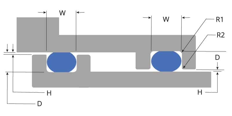


O Ring Groove Design Global O Ring And Seal
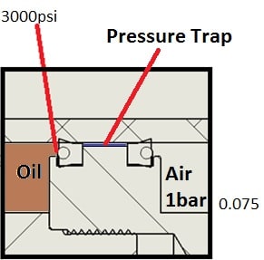


Hydraulic Cylinder Seal Configuration Back To Back Leaks Fluid Power Engineering Eng Tips
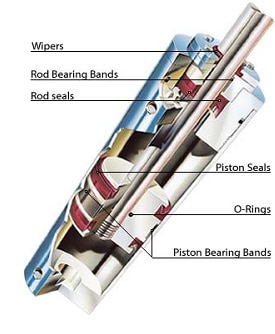


Hydraulic Seals Allied Metrics Seals Fasteners Inc
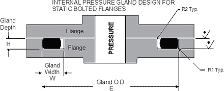


Static O Ring Face Seal Groove Design Guide


Newdealseals Com App Uploads 04 Newdealseals O Ring Handbook 14 Pdf
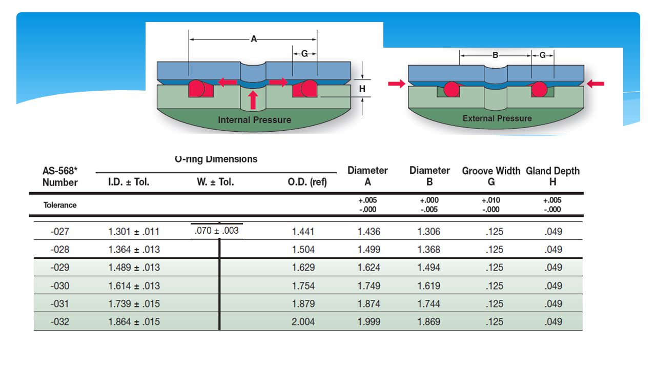


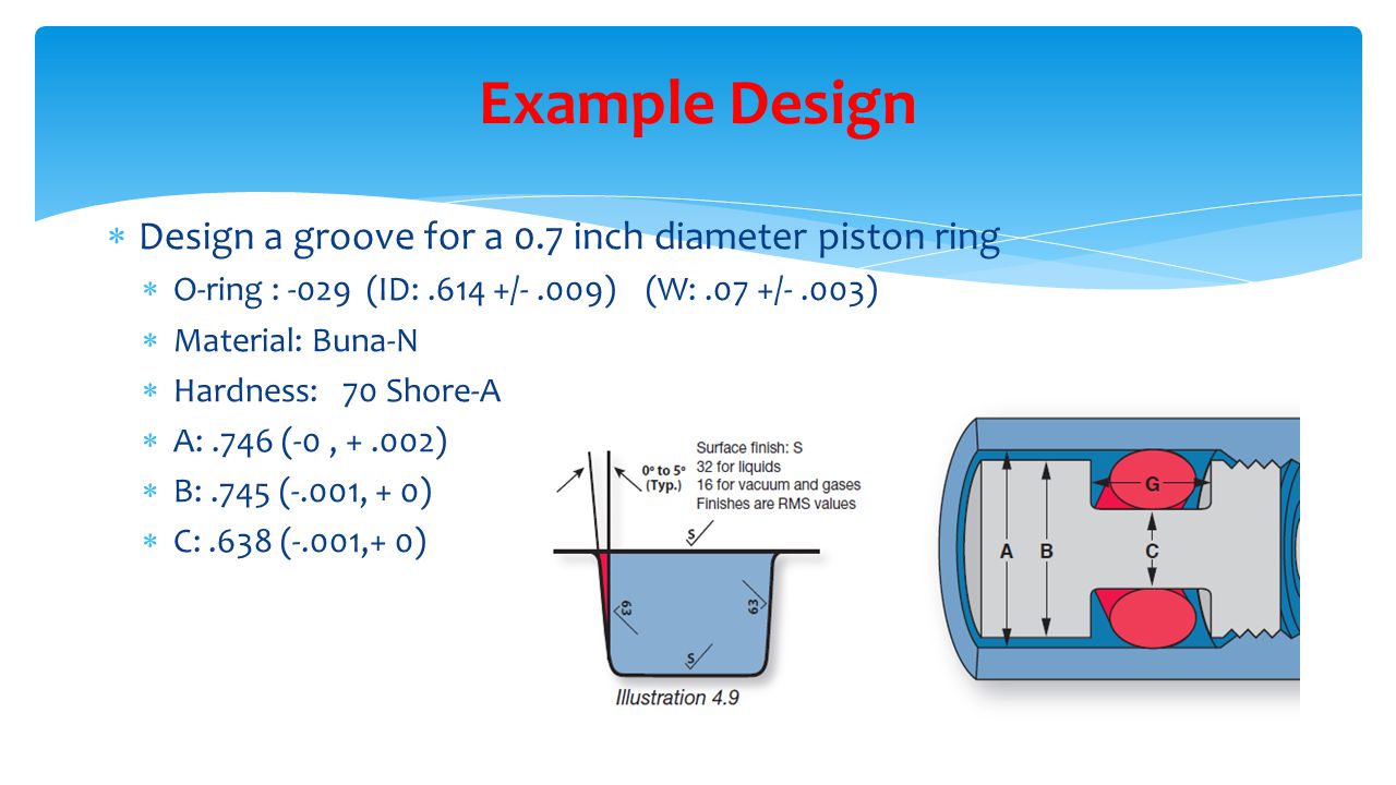
Design Of O Ring Seals Ppt Video Online Download
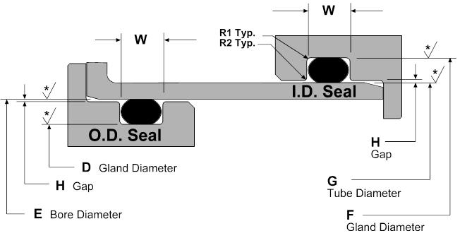


Static O Ring Groove Design A Rod And Piston Glands
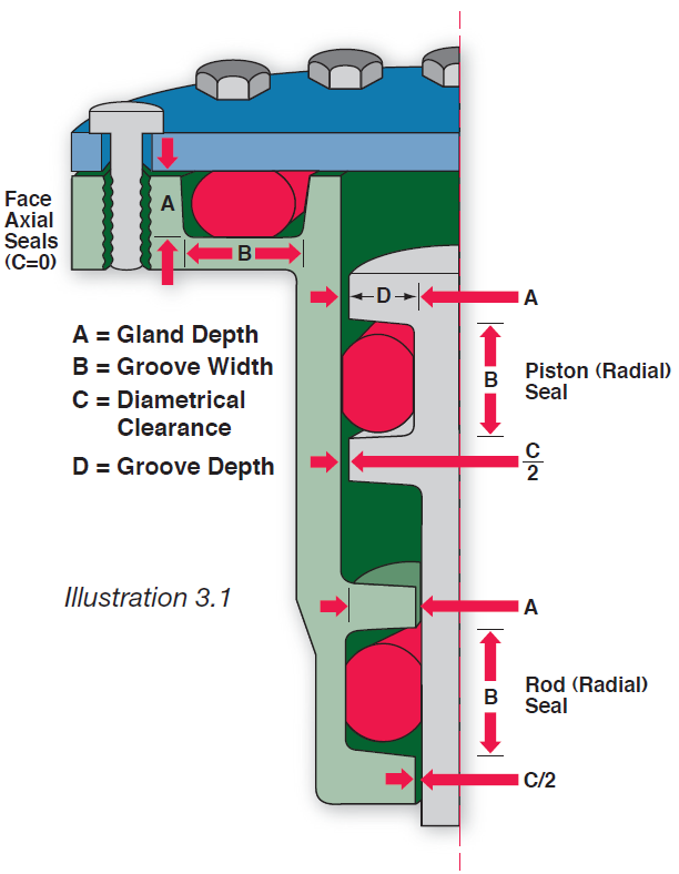


Fundamental Of O Ring


Busak Shamban Piston Seals Turcon Aq Seal
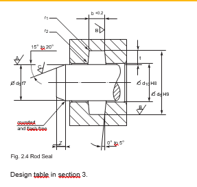


2 Design And Detail Information O Rings Stock O Ring Webshop
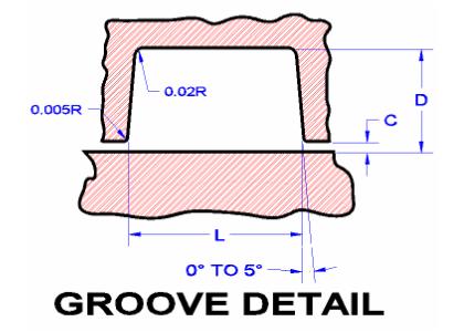


Seals Eastern O Ring Piston Seal Design Guideline


Http Practicalmaintenance Net Wp Content Uploads Working Design Considerations And Maintenance Of O Rings Pdf


Static O Ring Gland Design A High Level Run Down By Sean Thomas Linkedin


O Ring Lusida Rubber Products


O Rings O Yeah How To Select Design And Install O Ring Seals Tarkka
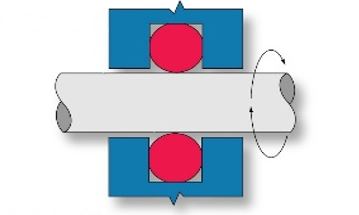


What You Need To Know About Dynamic Seal Applications Hot Topics


Seal Solutions Guide
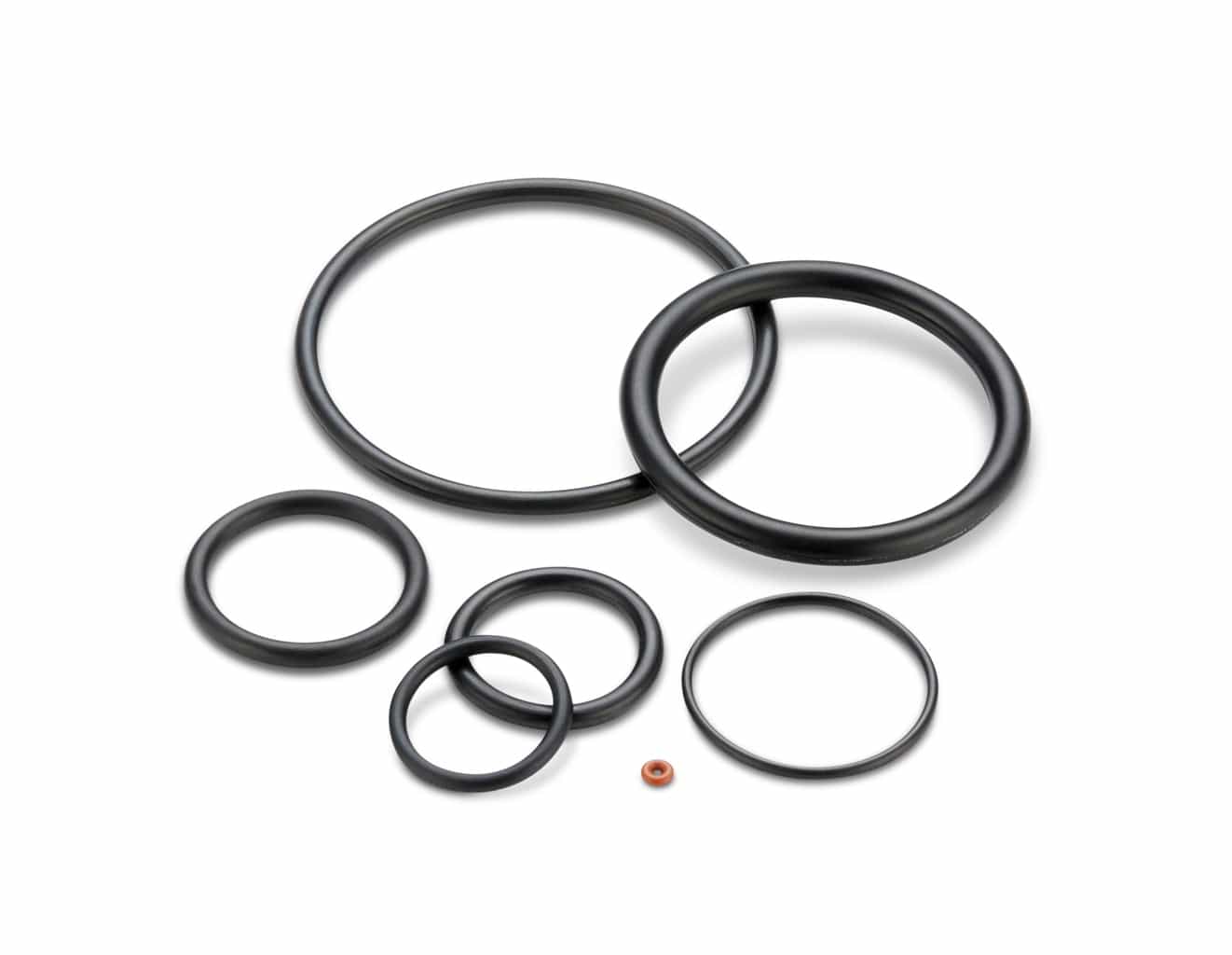


Groove Design O Ring Seals Minnesota Rubber Plastics
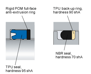


Gap Extrusion Skf Skf


The Assembly Of The O Rings Equipment For The Assembly Of The O Rings Elastotech S R L


Design Of Oring Seals Design Of Oring Seals
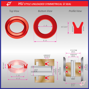


What Are U Cups U Seals Polypaks Rocket Seals Inc
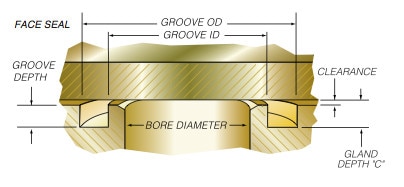


Quad Ring Face Seal Application Example Minnesota Rubber Plastics


Quad Rings All Seals
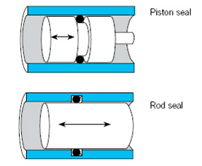


O Ring Gland Design Guide Oringstore Com


Dichtomatik Seal Category Piston Seal Hydraulic K70 Freudenberg Sealing Technologies


What You Need To Know About Dynamic Seal Applications Hot Topics


How To Properly Choose Commercially Available O Ring Cross Sections Performance Seals Inc


Design Of O Ring Seals Ppt Video Online Download


Oring Ehandbook


O Ring Wikipedia


Kumar Rubber Store


Seals And Sealing Technology Hydraulics Pneumatics


O Ring Groove Design Global O Ring And Seal


Dynamic Seal An Overview Sciencedirect Topics
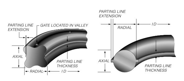


Advantages Of A Quad Ring Over An O Ring


Seal Design O Ring Design O Ring Design Guide


Would Slippery O Rings Or Seals Improve Your Product Performance


Seals


Ps1800 Piston Seal Assemblies Hercules For O Rings Hydraulic Seals Cylinders


0 件のコメント:
コメントを投稿